
News
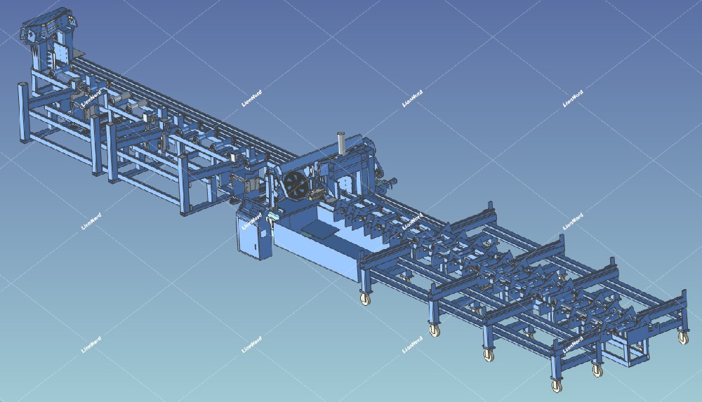
Fully automatic metal cutting band saw machine line
07 Sep February 2024 | LionNord
When using, users only need to place the workpiece to be sawed on the feeding rack, input the length and quantity to be cut, and the equipment will automatically cut according to the predetermined program. Move the feeding to the feeding rack, clamp the workpiece servo feeding, feed in place, clamp the front and rear jaws for sawing, return the blade after sawing, and then feed again (at the same time, the front moving jaws move the discharge head to the position of the front pushing device according to the length size - the pushing device starts to push out the material flat to the material head storage rack) - clamp the workpiece again, saw and cut it, and the finished product is electrically sent out to the flipping device in place. According to the input requirements, the material is flipped out on both sides to the storage rack with rollers, and this process is repeated until the workpiece is sawed to the preset quantity.
The hydraulic clamp adopts a combination of high-quality oil cylinders and high-precision guide rods, with three sets of front and rear jaws to clamp the workpiece on both sides. The workpiece can enter the sawing position from the back of the sawing machine for sawing.
By combining electrical systems with servo and hydraulic systems, the workpiece can be quickly and accurately moved back and forth to complete sawing and positioning work. The drum type rack supports materials, with more precise positioning.
The unique hydraulic system adjusts the cutting speed through a speed control valve, which can prevent abnormal damage to the saw belt and achieve the best cutting effect.
The dual hydraulic cylinder design, combined with high-precision guide rail lifting, forms a stable sawing structure.
The entire oil circuit adopts a constant temperature system to make sawing smoother
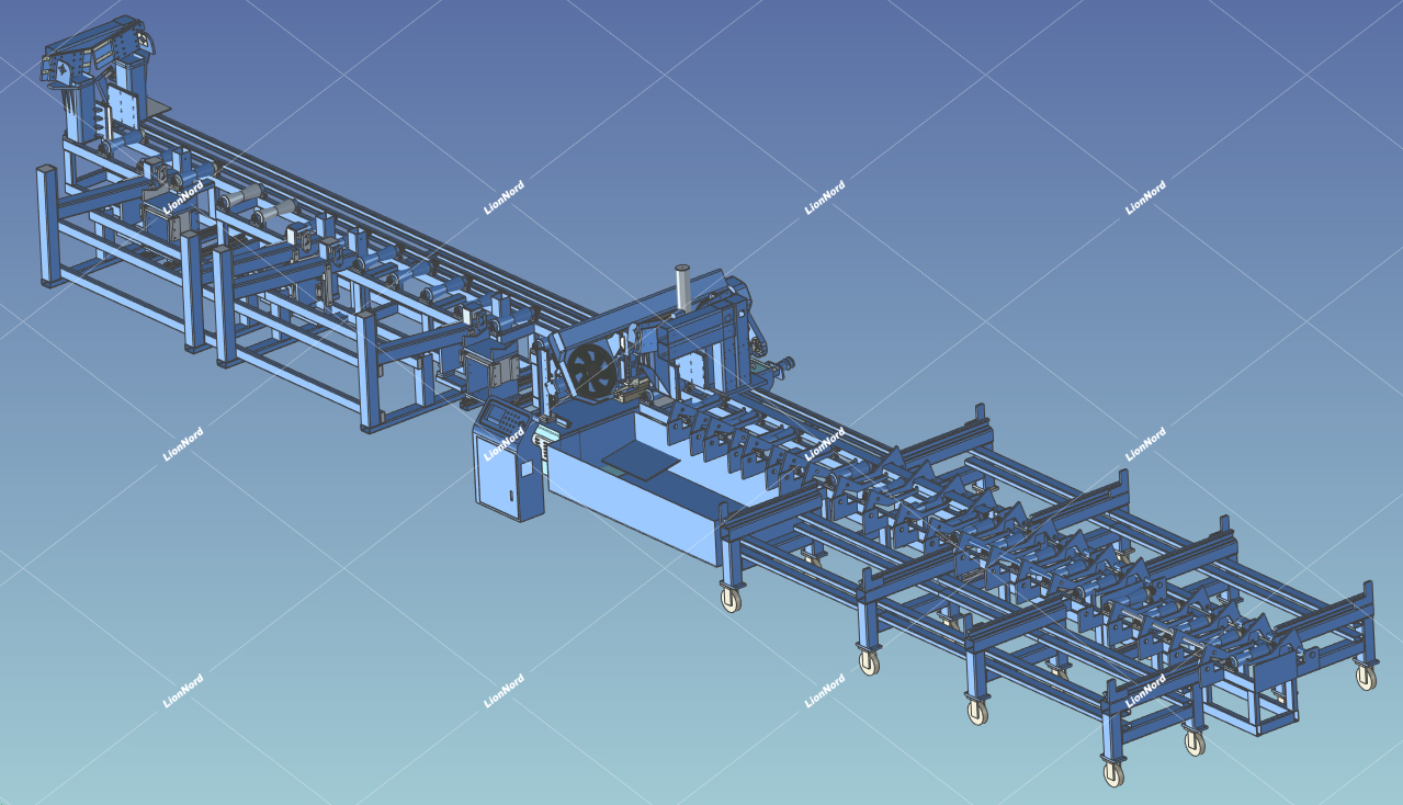
The main structure and process description of this machine tool are as follows:
1. Bed bucket section
The bed bucket is a box shaped welded structure with sufficient rigidity. It is equipped with a mobile workbench, clamping device, column base, cooling water tank, etc.
2. Column section
The surface is coated with hard chrome for tight grinding and is very wear-resistant. Its guide sleeve is made of self-lubricating wear-resistant material, which will not cause crawling during operation. The fit gap between the two is very small, the rigidity is good, and the verticality of the sawing section is good, ensuring the stability and accuracy of the sawing frame.
3. Main transmission part
Worm gear - made of tin bronze material and processed on a precision hobbing machine using precision worm gear cutters.
Worm - After quenching, it is ground and processed on a precision vortex bar grinder, with high surface smoothness and precision.
Box body - made of Mihana cast iron, with a dedicated boring die to ensure machining accuracy, and the worm gear box has a long service life.
4. Saw frame, hydraulic cylinder lifting part
The saw frame adopts a steel plate welded structure. The right pulley is the main driving wheel, the left pulley is the driven wheel equipped with a tensioning device, and the middle is equipped with a saw belt guide arm and a guide moving device. The saw belt iron filings are removed by a steel wire wheel. The lifting is driven by a combination of columns and hydraulic cylinders.
5. Guidance and moving device of saw belt
The saw belt is twisted by a guide device, and two sets of hard alloy guide blocks are installed inside the guide seat. The front and rear are equipped with bearing guide devices for fine adjustment.
6. Electrical box and electrical control box section
The electrical cabinet is a vertical cabinet type, placed on the left side of the sawing machine. The electrical components of the electrical box are centrally configured and installed inside, achieving stability and reliability of the electrical components, extending their service life, and greatly reducing the electrical failure rate. The electrical control buttons are located on the upper part of the control panel electrical box, and the entire machine tool can be operated through button control on the control panel. The entire electrical system is configured as follows: the frequency converter is selected from well-known domestic products, and the motor is selected from domestic Y series standard products.
7. Hydraulic pump station device part
Independent hydraulic pump station, hydraulic components adopt well-known domestic brands, oil tank capacity is about 80L or more, and the main pump of the hydraulic station is a variable pump.
8. Cooling device
The cooling device is installed on the side of the bed, and the water chamber is dispersed to various parts of the cooling device required by the water pump on the bed of the main engine, which can automatically return to the storage tank pump station for automatic circulation.
9. Feed storage rack
Composed of one set of chain discharge brackets, the storage rack can hold three neatly placed materials.
10. Loading mechanism
Composed of a mobile car and a lifting mechanism, the mobile car is equipped with a lifting mechanism, which is driven by an oil cylinder. Install 2 sets of mobile carts on the feeding rack. When the mobile cart stops at the loading position, the lifting mechanism lifts up and lifts up the raw materials; After the mobile cart advances to the feeding roller conveyor, the lifting mechanism descends to place the raw materials on the feeding roller conveyor.
11. Feeding device
This machine tool adopts a vise clamping forward feeding method, and the roller conveyor is a free roller conveyor. The clamping vise moves on a linear guide through servo drive combined with gears and racks. The feeding length detection adopts a servo encoder, and the single feeding stroke is 6000mm. The feeding vise is clamped in the center to improve the feeding accuracy.
12. Front pull jaw
There is a set of front pull clamp pliers designed at the front end of the sawing machine. The front pull jaw clamps the material head by moving the clamp.
13. Discharge roller conveyor
For the convenience of supporting long finished products, an electric material rack is designed at the front of the sawing machine. After sawing is completed, the electric material is fed to the positioning point, and the material is detected to be in place and flipped out to the front left and right storage racks.
14. Material cutting mechanism
There are two sets of mechanisms installed on the discharge rack to move the finished products after sawing to the finished product storage rack, driven by oil cylinders.
15. Finished product storage rack
Composed of 2 sets of brackets, each side can store 3 finished products with a diameter of 275mm.
 English
 chinese
